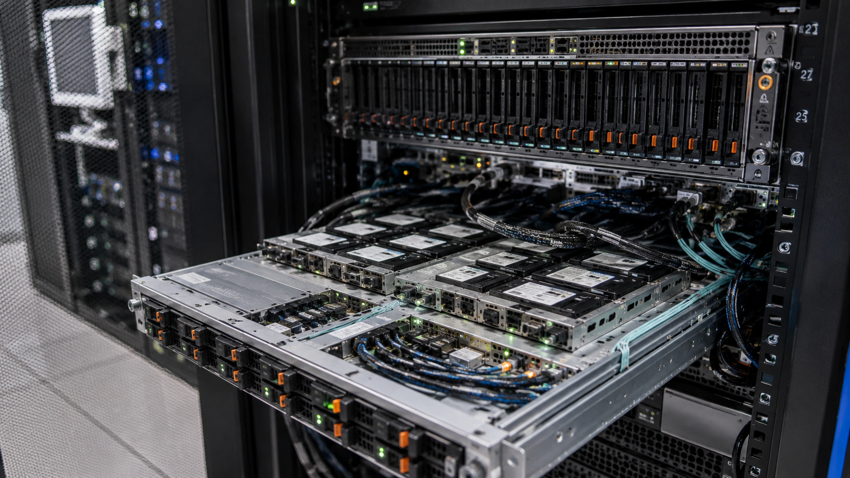
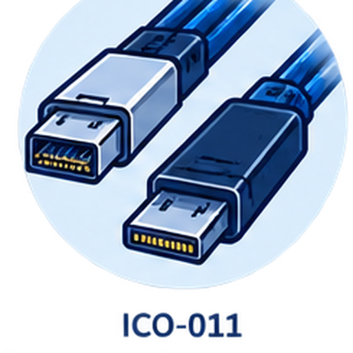
 01
01Exact OCuLink connector form
Provide the equipment-side connector reference, keying, mating interface, photo or drawing. OCuLink is not treated as one universal physical endpoint.
A cross-family RFQ starting point for OCuLink endpoint projects. Select the source connector route, then confirm the exact OCuLink form, equipment roles, lane topology, mapping, orientation and chassis routing before quotation.
Endpoints Application
 Drawing / sample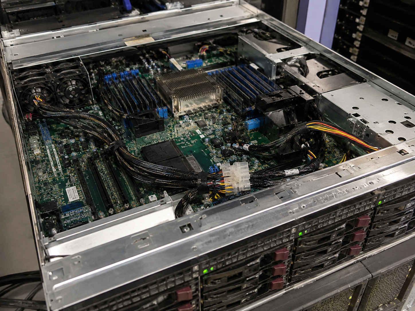
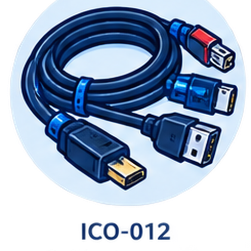 2Product pages2Source connector routes1Application-led review
 1Coordinated RFQ path
The available options connect OCuLink to either MCIO or Mini SAS HD SFF-8643. Choosing between them requires the actual source connector, host-to-target relationship, topology and mechanical installation—not an assumption based on connector appearance.
Each product page retains its original catalog family and evidence boundary while this page provides one OCuLink-centered selection path.
Partial information is welcome. Unknown connector form, topology or wiring becomes a focused review question before quotation.
01Provide the equipment-side connector reference, keying, mating interface, photo or drawing. OCuLink is not treated as one universal physical endpoint.
02Identify the controller, adapter, backplane and target device at both ends so direction is established from the system path.
 03
03State the required lane count, breakout or aggregation topology and any mapping evidence supplied by platform documentation.
04Confirm whether the other endpoint is MCIO or Mini SAS HD SFF-8643. Similar application language does not make the routes interchangeable.
 05
05Share connector exit, assembly length, bend path, retention, clearance and service-loop needs inside the installation.
06Attach drawings, manuals, wiring tables or an existing sample where pinout, sideband signals, protocol or performance must be confirmed.

Identify the controller, adapter, backplane or target device on the OCuLink side and the equipment on the MCIO or SFF-8643 side. A block diagram or platform manual can resolve direction, topology and connector-form questions before a cable is selected.
 Controller and targetExact connector formsLane topology and mappingDrawing, manual or sample
Use the closest available option; use Custom Cable when the source connector or required mapping is not represented.
Record the controller, adapter, backplane and target relationship.
Choose MCIO or SFF-8643 at the source and document the exact OCuLink mating interface.
Clarify direction, lane mapping, pinout boundary, exit, length and chassis routing.
Coordinate the next step according to project stage, quantity and confirmed evidence.
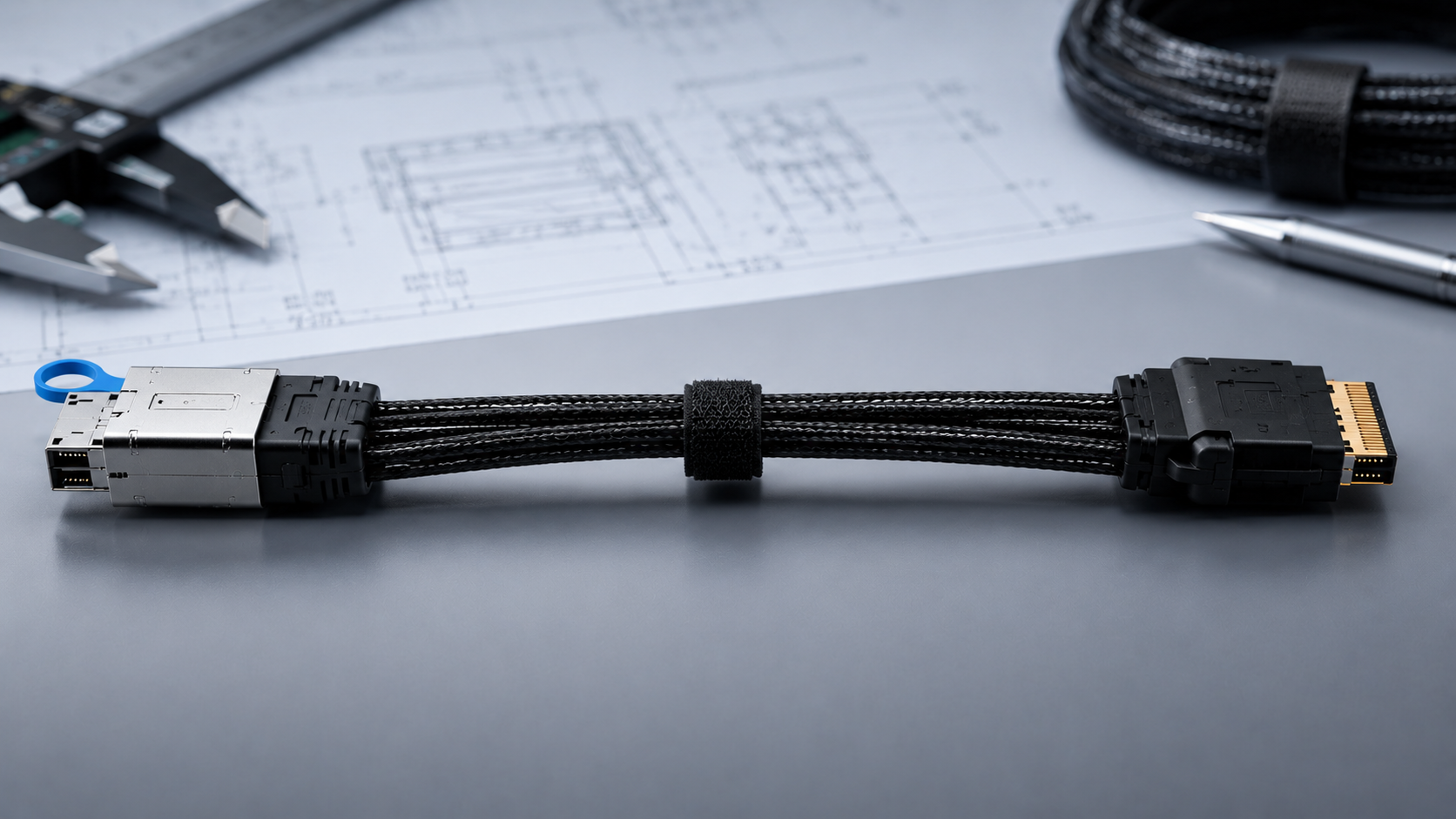
A connector photo can help identify the family but cannot prove direction, wiring or compatibility. Submit both equipment roles, available references, required quantity and installation constraints so the project can be matched correctly.
01Endpoints02Review 03Partner04Quote