 01
01System and application context
Identify the controller, motherboard, backplane, drive or device at both ends—and what the connection must accomplish.
An RFQ starting point built around your requirement for SlimSAS 4i, 8i, device-side and breakout cable projects. Compare available configurations and identify the direction, topology and mechanical details that require confirmation.
 EndpointsApplication
 Drawing / sample
 4Product pages4i / 8iConfiguration routes1Application-led review
 1Coordinated RFQ path
SlimSAS projects can involve 4i or 8i connectors, straight-through assemblies, U.2 device paths, SATA breakouts and different orientation or direction requirements. This page provides clear product options without treating similar-looking cables as interchangeable.
Use the family pages for initial routing. The product-detail pages will be expanded individually in the next stage.
Drive count, power and topology need confirmation.
Review configuration →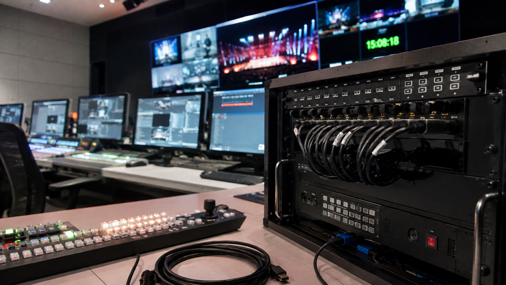
Breakout direction, exit and SATA orientation can mismatch.
Review configuration →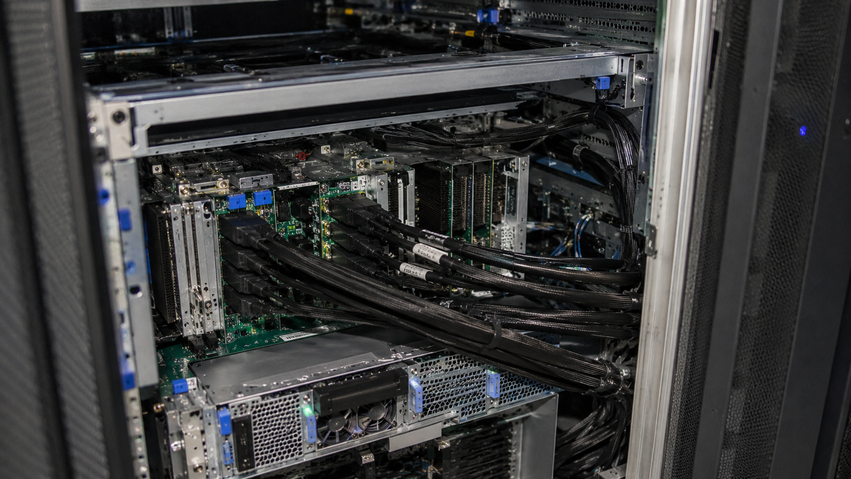
Endpoint, orientation and breakout configuration vary.
Review configuration →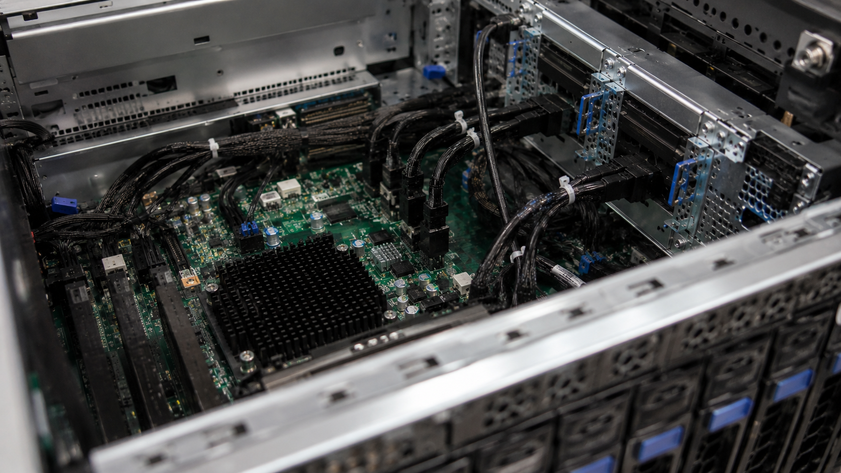
Space constraints and endpoint choice drive the requirement.
Review configuration →You can begin with incomplete information. Known inputs are recorded, and missing direction, endpoint or mechanical details become focused review questions.
01Identify the controller, motherboard, backplane, drive or device at both ends—and what the connection must accomplish.
02Provide the exact SFF reference, lane requirement and connector form. A SlimSAS name or photo alone is not enough.
03Clarify whether the assembly stays within one connector family or breaks out to U.2, SATA or another endpoint.
 04
04State the host-to-target relationship and required topology. Forward, reverse and mapping details are reviewed from evidence.
 05
05Share straight or angled connector needs, cable exit, target length, bend path and chassis clearance.
06Platform documentation, a wiring diagram, connector photos or an existing sample can prevent an expensive mismatch.
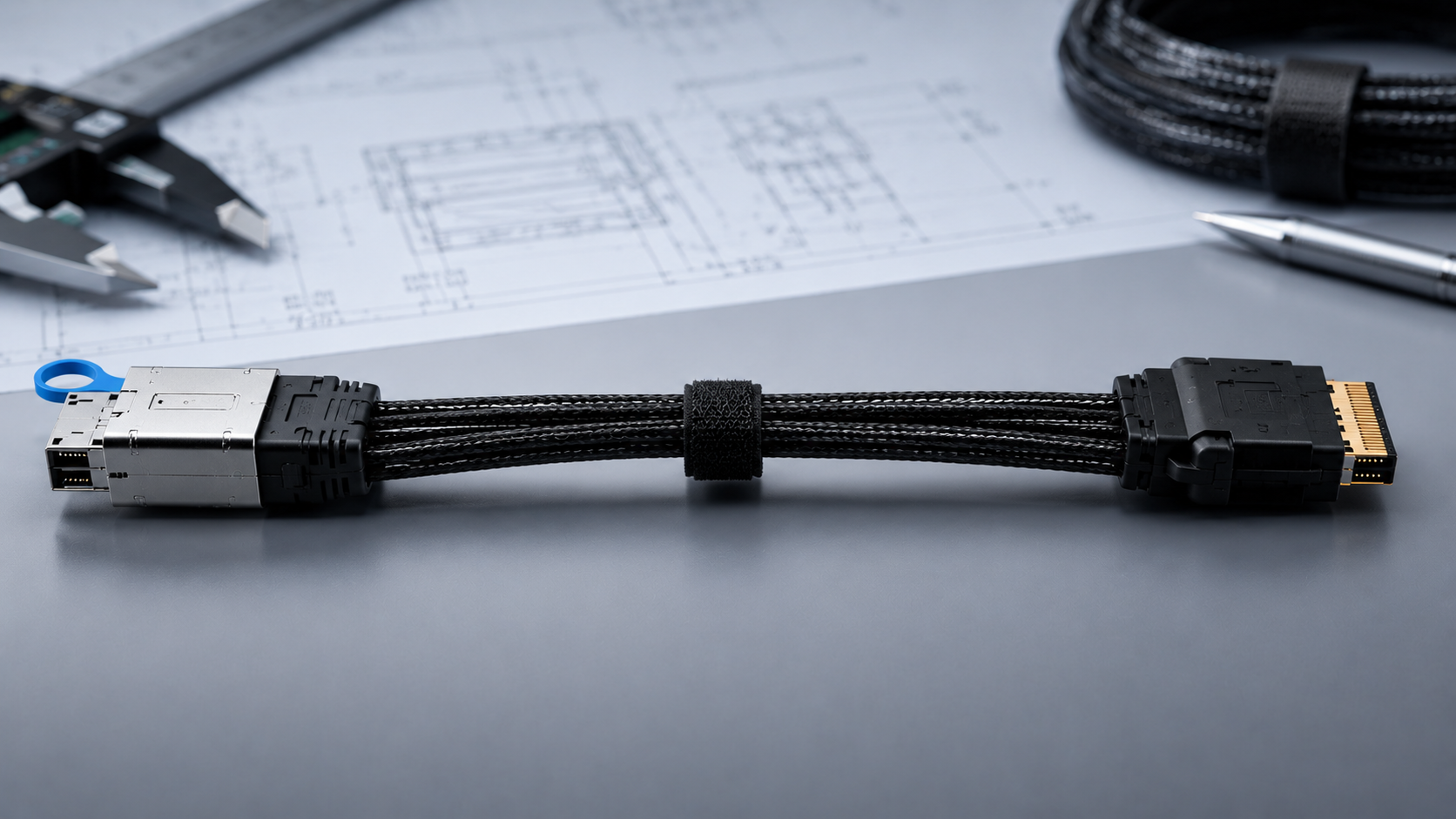
A 4i or 8i connector label does not establish whether the cable is straight-through, breakout, forward, reverse or mapped for a specific platform. Tell us where both ends connect and attach any available drawing, photo or existing sample.
 Controller, backplane or driveExact connector referencesDirection and topologyDrawing, photo or sample
Start with the closest known configuration; use Custom Cable when the endpoint combination or mapping is not represented.
Record the connector form and required lane arrangement without assuming performance.
Identify U.2, SATA, SlimSAS or another actual target connection.
Review host-to-target path, mapping, orientation, length and chassis routing.
Coordinate the next step according to project stage, quantity and evidence.

Connector photos can help, but they cannot prove direction or mapping. Submit the equipment relationship, available references, required quantity and mechanical constraints so the project can be matched correctly.
01Endpoints02Review 03Partner04Quote