 01
01Host platform and slot architecture
Identify the motherboard, server, riser, switch or host adapter and the physical/electrical slot relationship documented by the platform.
An application-led RFQ starting point for GPU, accelerator, NIC, storage and expansion-system interconnect projects. Define the host architecture, endpoint, lane topology, connector system, power boundary and chassis installation before quotation.
 Endpoints
 Application
 Drawing / sample
 GPU / NICExpansion endpointsHost → targetArchitecture first
 Signal / powerDefined boundary
 1Coordinated RFQ path
PCIe describes an interconnect architecture, not one universal cable assembly. A usable RFQ must connect the host platform, endpoint device, lane requirement, connector system and physical installation into one reviewed equipment path.
These are requirement categories—not published universal products. The exact connector combination is established from equipment documentation and project evidence.
RFQ ROUTEConnect a host, riser, switch or expansion platform to a defined GPU or accelerator endpoint.
Useful RFQ inputsHost model · Endpoint model · Lane topology · Slot locationStart technical RFQ →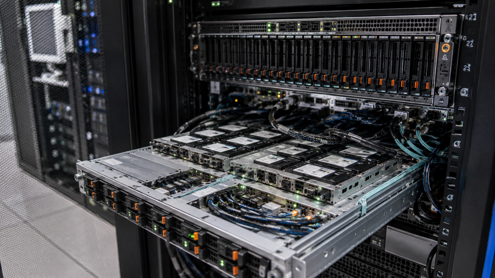 RFQ ROUTE
Route a network or storage adapter where chassis position, airflow and service access affect the assembly.
Useful RFQ inputsAdapter model · Host slot · Cable path · RetentionStart technical RFQ →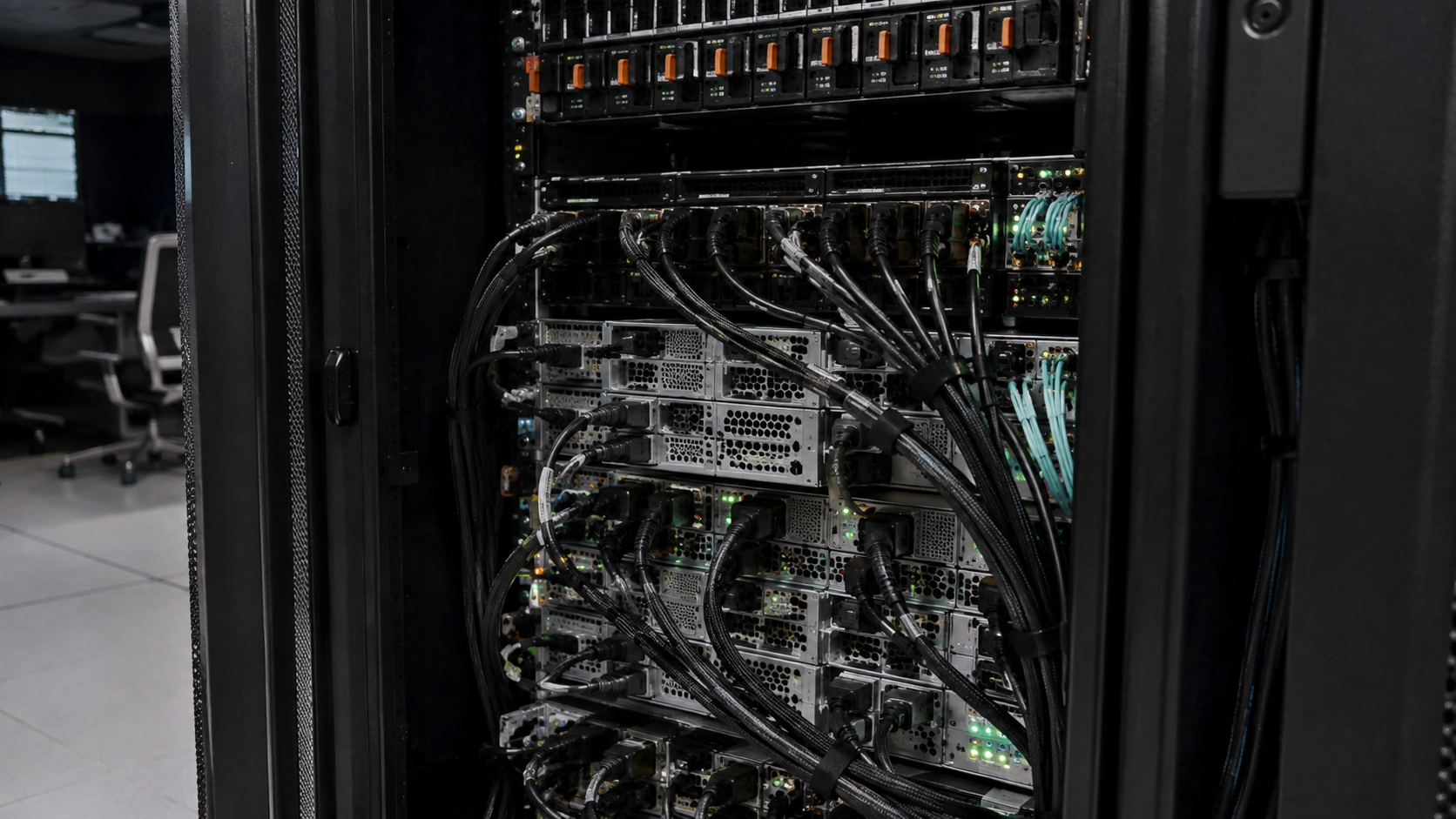 RFQ ROUTE
Define a board-to-board path through risers, backplanes or internal expansion modules.
Useful RFQ inputsBoard references · Connector drawings · Mapping · LengthStart technical RFQ →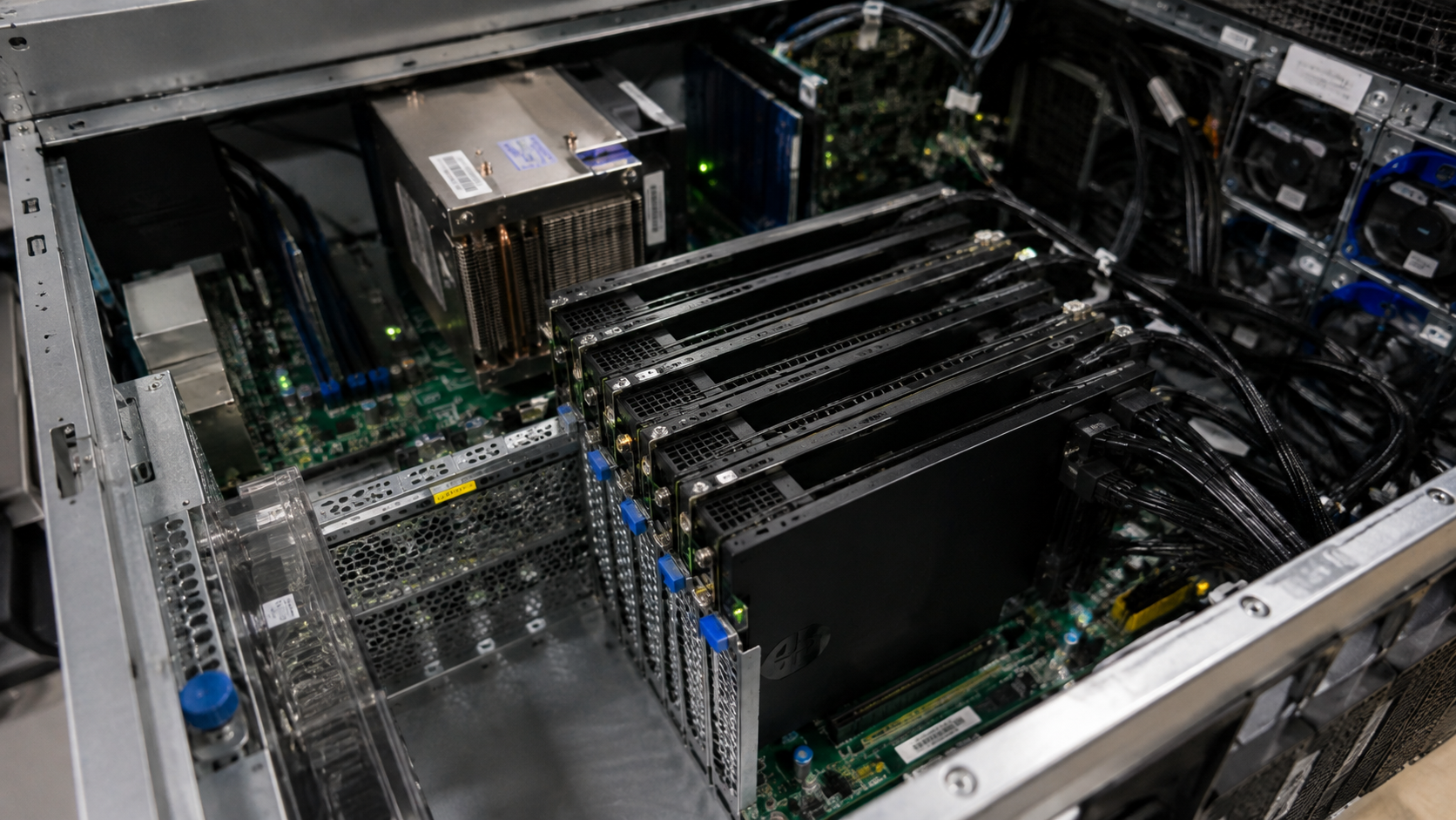 RFQ ROUTE
Begin from a block diagram or existing sample when no public product route exactly represents the platform.
Useful RFQ inputsDrawing · Pinout evidence · Quantity · Project stageUse Custom Cable Entry →Unknown fields do not block the first review. They become explicit questions before a connector route or performance statement is accepted.
01Identify the motherboard, server, riser, switch or host adapter and the physical/electrical slot relationship documented by the platform.
02Name the GPU, accelerator, NIC, storage adapter or other endpoint and the lane topology the equipment requires.
03Provide the exact board, riser or adapter connector references, keying, mating interface and retention method at both ends.
 04
04Confirm source-to-endpoint direction, bifurcation, aggregation and lane mapping from approved platform documentation or drawings.
05Separate signal-cable scope from any auxiliary power path, then define exit, length, bend radius, airflow and chassis clearance.
06Attach system manuals, schematics, pinout tables, compliance needs or an existing assembly before generation or performance claims are applied.
Tell us where the PCIe path begins, whether a riser, switch, backplane or adapter sits between the endpoints, and where the target device is mounted. This equipment map is more useful than selecting a connector from appearance alone.
Host platform and slotGPU, NIC or adapterTopology and lane mappingManual, drawing or sampleA PCIe signal interconnect request may sit beside a separate auxiliary power requirement. The RFQ records each interface, conductor path and equipment responsibility explicitly.
Record the host, intermediate boards, endpoint and documented lane topology.
Identify whether auxiliary device power is outside the cable, a separate harness or part of a documented assembly.
Review connectors, pinout evidence, length, shielding needs, bend path, airflow and retention.
Coordinate supplier review, questions and the next step according to quantity and project stage.
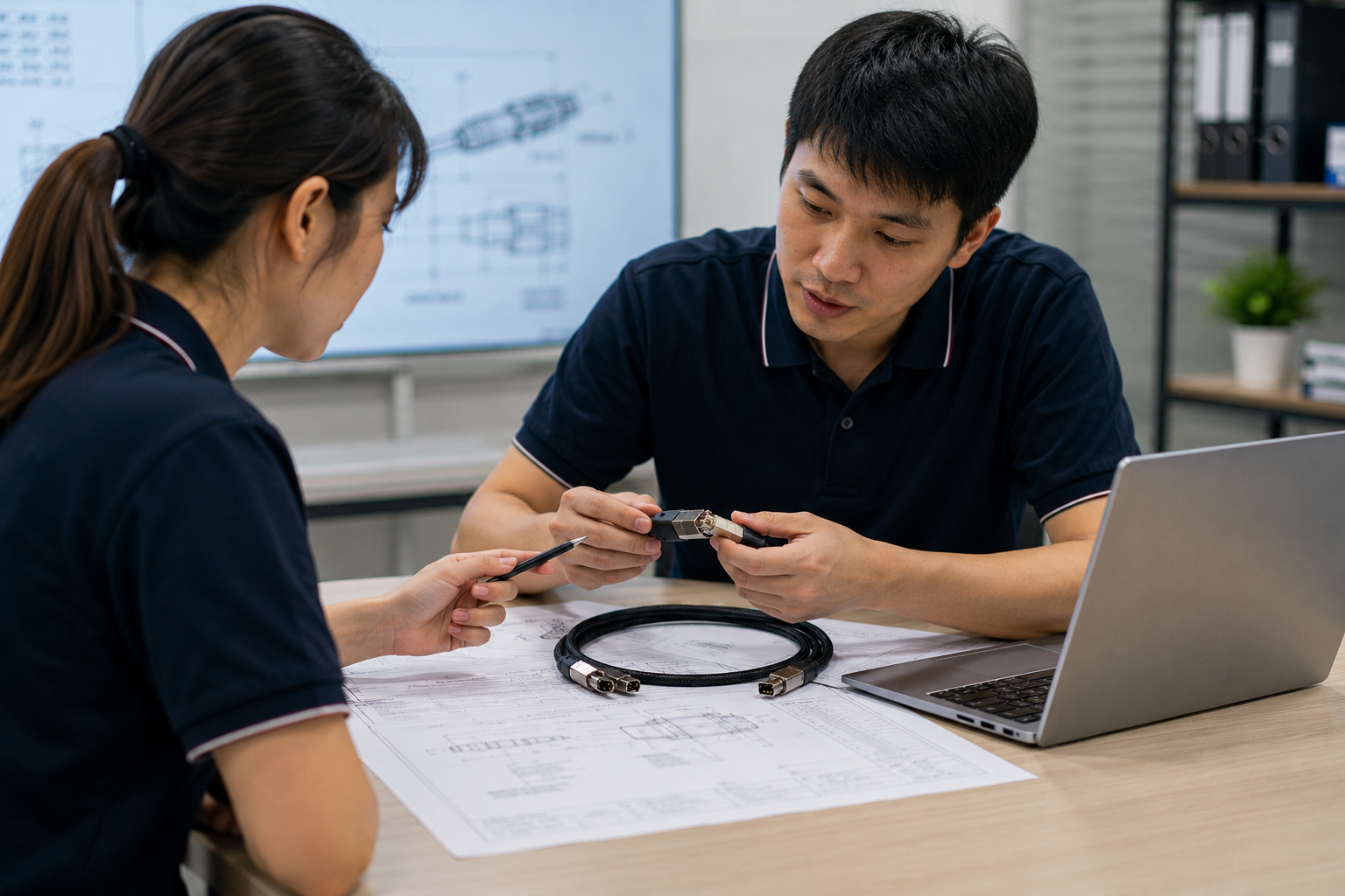
A motherboard model, endpoint model, riser or backplane reference and installation photo are enough to begin. We will separate the known architecture from the connector, mapping and performance details that still need evidence.
01Endpoints02Review 03Partner04Quote