 01
01Controller-to-target path
Identify the host bus adapter, motherboard, backplane, drive, adapter or other endpoint—and the complete signal path between them.
An RFQ starting point built around your requirement for high-density server and storage cable projects. Compare approved SFF-8643 routes to SATA, U.2 and OCuLink, then confirm direction, topology, mapping and mechanical fit before quotation.
 EndpointsApplication
 Drawing / sample
 3Product pagesSFF-8643Launch connector route3Target families
 1Coordinated RFQ path
Mini SAS HD requirements can differ by internal or external connector form, target device, consolidated or breakout topology, direction and mechanical environment. The available routes below center on SFF-8643 without treating every high-density SAS-family cable as interchangeable.
Each route begins with a endpoint combination. Exact direction, device count, mapping, power and fit remain part of project review.
Forward/reverse direction and exit angle are common failure points.
Review configuration →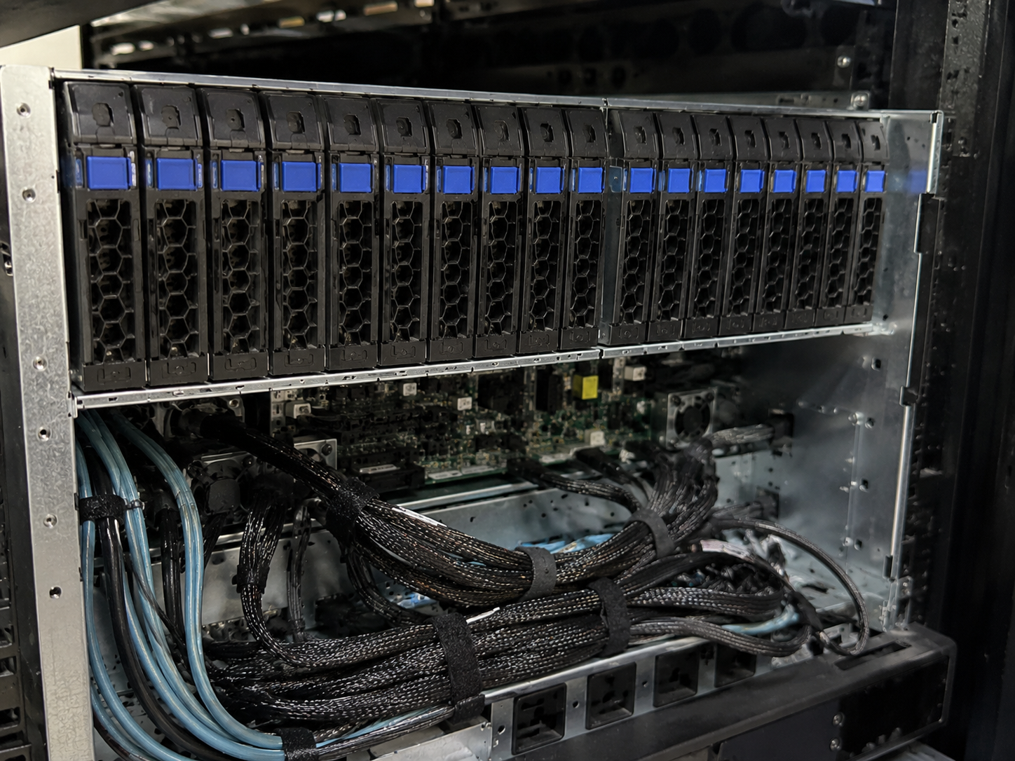
U.2 count, power and terminology require careful matching.
Review configuration →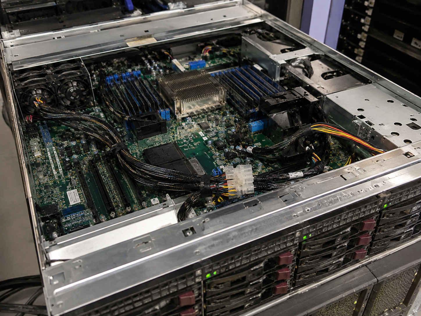
Host/target direction confusion can make the cable unusable.
Review configuration →Incomplete information is acceptable. Unknown connector, direction, topology or space constraints become explicit review questions.
01Identify the host bus adapter, motherboard, backplane, drive, adapter or other endpoint—and the complete signal path between them.
02Confirm SFF-8643 or another Mini SAS HD connector, both mating interfaces, keying and whether each connection is internal or external.
03State whether the assembly remains consolidated or breaks out to SATA, U.2, OCuLink or another approved endpoint.
 04
04Define host and target roles. Forward, reverse, lane mapping and protocol compatibility are reviewed from project evidence.
 05
05Share connector angle, cable exit, target length, bend path, strain relief, chassis clearance and serviceability needs.
06Platform documentation, wiring diagrams, connector photos and cable labels can resolve terminology and direction before quotation.
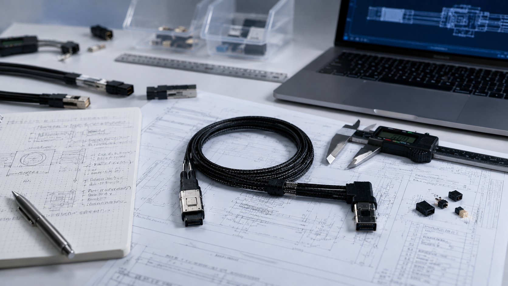
Tell us what the SFF-8643 side connects to, the exact target endpoint, and whether a backplane, adapter, breakout or device-power path is involved. A controller model, block diagram or existing cable label can prevent a direction or terminology mismatch.
 Controller and target devicesExact endpoint referencesDirection and topologyDrawing, photo or sample
Use the closest available option; use Custom Cable when the connector combination or mapping is not represented.
Record connector location, SFF reference, mating interface and host platform.
Choose SATA, U.2, OCuLink or describe another required endpoint.
Clarify host-to-target direction, topology, mapping, power boundary, orientation and routing.
Coordinate the next step according to project stage, quantity and confirmed evidence.

A connector photo helps identify the family but cannot establish direction, wiring or compatibility. Submit the platform relationship, available references, quantity and installation constraints so the project can be matched correctly.
01Endpoints02Review 03Partner04Quote