 01
01Host, adapter and target relationship
Identify the controller, motherboard or backplane on the SFF-8643 side and the adapter, drive, backplane or other equipment reached through OCuLink.
An RFQ page built around your requirement for SFF-8643 to OCuLink interconnect projects where the exact OCuLink endpoint, host-to-target direction, lane topology, pinout, protocol boundary and chassis fit must be confirmed before quotation.
 EndpointsApplication
 Drawing / sample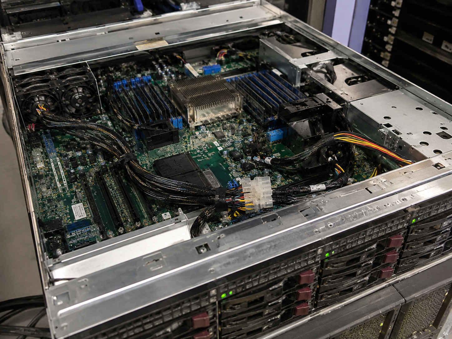
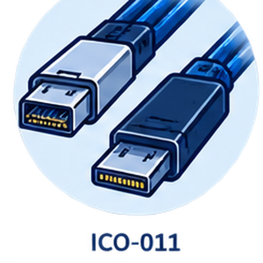
Our catalog includes Mini SAS HD SFF-8643 to OCuLink under reference P04-014. It does not establish universal direction, connector form, pinout, lane mapping, protocol, performance, length or platform compatibility.
Partial information is welcome. Unknown direction, topology or mechanical details become explicit review questions before quotation.
01Identify the controller, motherboard or backplane on the SFF-8643 side and the adapter, drive, backplane or other equipment reached through OCuLink.
02Provide the OCuLink connector reference, mating equipment, keying, orientation, photos or drawings. The family name alone does not define the complete endpoint.
 03
03State which equipment is the source and target. Bidirectional compatibility is not assumed from the connector combination.
04Describe the required lane relationship and intended system path. Mapping and protocol compatibility are reviewed from applicable platform evidence.
 05
05Share both connector orientations, straight or angled exits, target length, bend constraints, chassis clearance and serviceability needs.
 06
06Provide prototype quantity, forecast and whether the project is at design, validation, pilot or production stage.
The correct cable must follow the actual host-to-target path, verified wiring and installation geometry.
The cable is wired for a different equipment relationship or signal direction than the project requires.
The endpoint form, keying or orientation does not match the adapter, backplane or target equipment.
Lane assignment, pinout or protocol compatibility is inferred from appearance instead of platform evidence.
Connector angle, cable exit, length or bend path conflicts with cards, fans, panels or chassis service access.
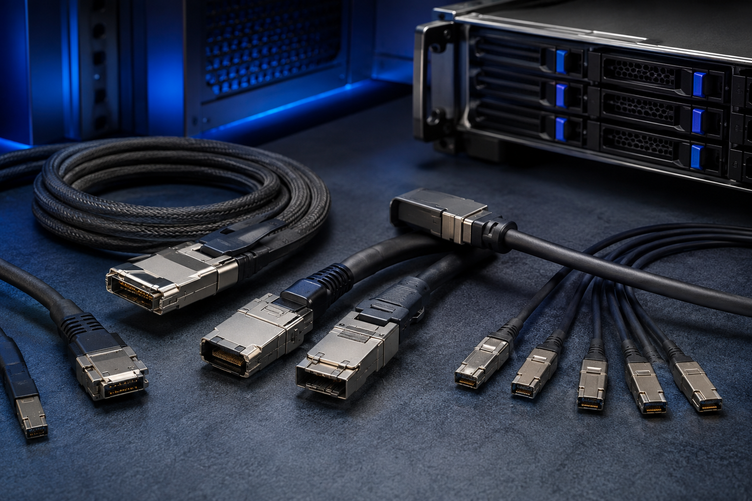
Tell us what equipment connects at both ends, whether an adapter or backplane sits in the path, and how the cable must route through the chassis. A platform block diagram, connector drawing, equipment manual or existing sample can resolve direction and mapping questions quickly.
 Host and target equipmentExact OCuLink endpointDirection and lane topologyDrawing, photo or sample
We start with the host, OCuLink target, quantity and available reference material.
Clarify endpoint form, direction, topology, pinout, protocol boundary and mechanical constraints.
We take the clarified configuration to a suitable manufacturing partner.
We then recommend a quote or sample step that fits the project stage.
If OCuLink is not the real target, use the four-SATA or U.2 route instead of forcing this configuration.
01Endpoints02Review 03Partner
 04Quote