 01
01Controller, backplane and U.2 device path
Identify the host bus adapter, motherboard or backplane on the SFF-8643 side and the exact U.2 device or intermediate hardware at the target side.
An RFQ page built around your requirement for SFF-8643 to U.2 storage interconnect projects where the exact U.2 endpoint, controller-to-device path, data and power boundary, pinout, orientation and chassis fit must be confirmed before quotation.
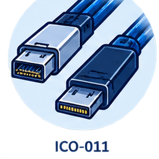 EndpointsApplication
 Drawing / sample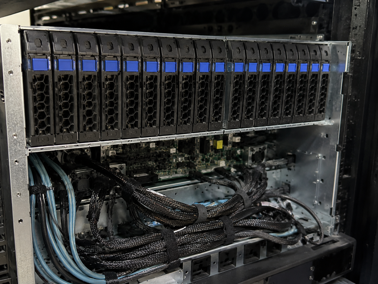

Catalog reference P04-013 supports Mini SAS HD SFF-8643 to U.2 as an RFQ configuration family. It does not prove universal pinout, protocol compatibility, power wiring, performance, length, orientation or platform compatibility.
Partial information is welcome. Unknown topology, wiring or power details become explicit review questions before quotation.
01Identify the host bus adapter, motherboard or backplane on the SFF-8643 side and the exact U.2 device or intermediate hardware at the target side.
02Provide connector references, equipment models, photos or drawings. Confirm the device-side U.2 / SFF-8639 mating form rather than relying on a product title alone.
 03
03State which equipment is the host and which is the target. Direction, pinout and lane mapping are reviewed from platform or verified wiring information.
 04
04Clarify whether the requested assembly carries only the data path or also includes a defined device-power connection. Provide the applicable platform documentation.
 05
05Share the SFF-8643 cable exit, U.2 plug orientation, target length, bend constraints, drive-bay clearance and serviceability needs.
 06
06Provide prototype quantity, forecast and whether the project is at design, validation, pilot or production stage.
The usable assembly depends on the actual controller-to-device architecture, verified wiring and physical installation path.
The device-side connector or mating arrangement differs from the actual drive, backplane or adapter requirement.
The project expects a power connection that is not part of the approved assembly—or assumes power details without platform evidence.
The host-to-target relationship, pinout or lane mapping does not match the controller and U.2 device path.
Connector orientation, cable exit, length or bend path conflicts with the chassis, drive carrier or adjacent hardware.
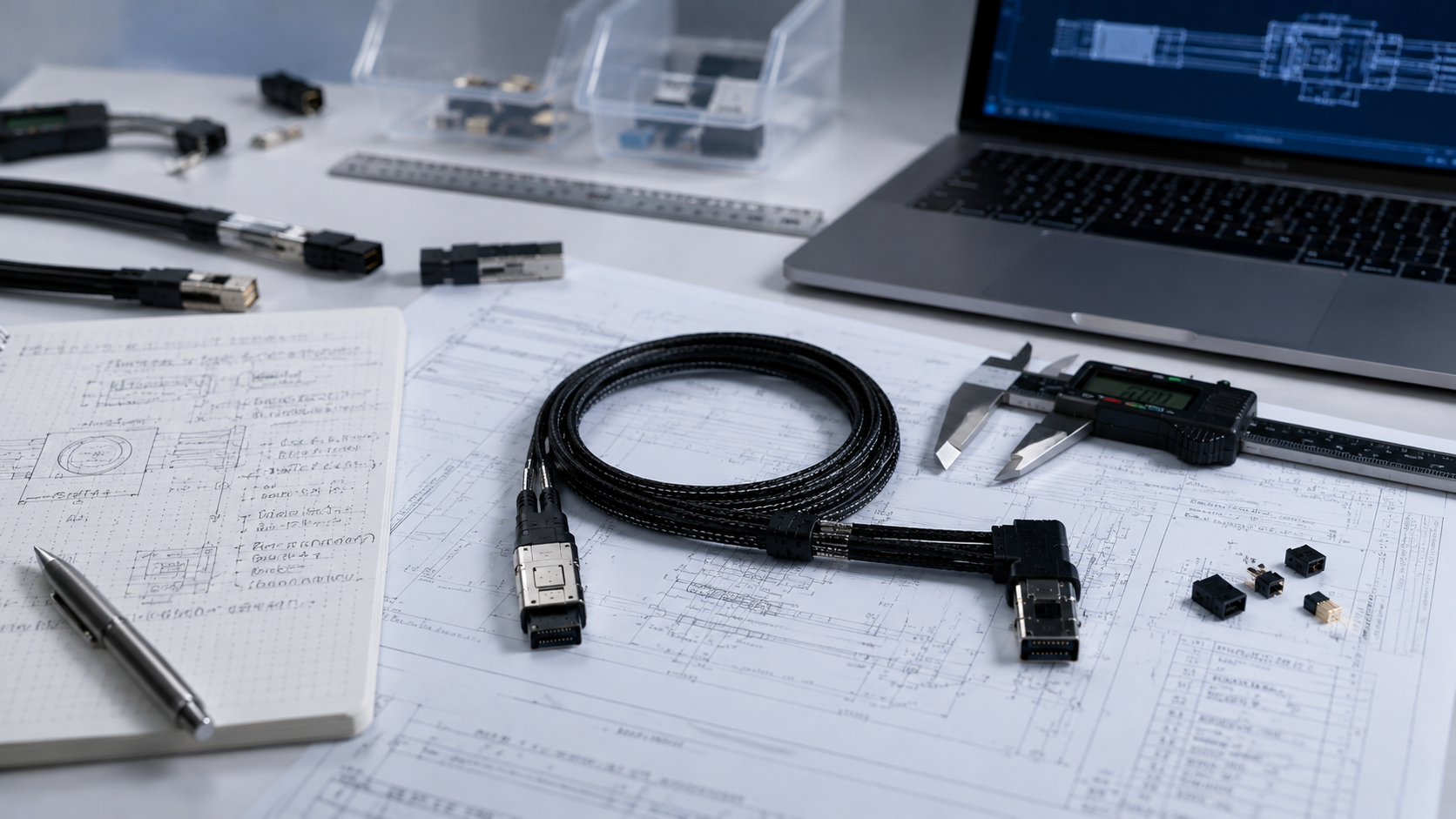
Tell us whether the path is direct or passes through a backplane or adapter, and identify any separate or integrated power connection. A controller manual, platform block diagram, cable drawing or existing sample can resolve terminology and wiring questions quickly.
Controller and target deviceExact U.2 mating interfaceData and power evidenceDrawing, photo or sampleWe start with the controller, U.2 target, quantity and available reference material.
Clarify mating interfaces, topology, direction, pinout, power scope and mechanical constraints.
We take the clarified configuration to a suitable manufacturing partner.
We then recommend a quote or sample step that fits the project stage.
If U.2 is not the real target, use the four-SATA or OCuLink route instead of forcing this configuration.
01Endpoints02Review 03Partner
 04Quote