 01
01Host and target relationship
Identify the motherboard, controller, backplane, adapter, drive or other endpoint at each end of the intended connection.
An RFQ page built around your requirement for compact SlimSAS SFF-8654 4i internal cable projects where the opposite endpoint, direction, lane mapping, connector orientation, length and chassis clearance must be confirmed before quotation.
 EndpointsApplication
 Drawing / sample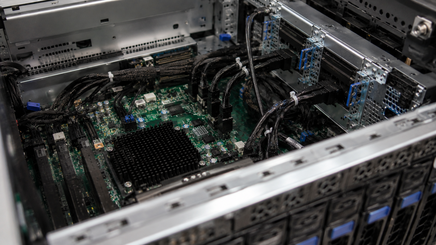

Our catalog lists SlimSAS SFF-8654 4i cable assemblies under references P03-010 through P03-016. They do not establish one fixed opposite endpoint, pinout, direction, data rate, length or platform compatibility.
You can begin with incomplete information. Unknown endpoint, mapping or clearance details become focused review questions before quotation.
01Identify the motherboard, controller, backplane, adapter, drive or other endpoint at each end of the intended connection.
02Provide SFF references, keying, mating details, photos or drawings for both endpoints—not only the SFF-8654 4i side.
 03
03State the host-to-target direction and required signal path. Pin and lane mapping are confirmed only from applicable project evidence.
 04
04Confirm straight or angled forms, latch access, plug orientation and the direction the cable must leave each connector.
05Share target length, bend constraints, adjacent hardware, airflow zones and available clearance inside the chassis.
 06
06Provide prototype quantity, forecast and whether the project is at design, validation, pilot or production stage.
The usable 4i assembly must match both the electrical path and the limited mechanical space inside the actual platform.
The cable terminates in a different connector, keying or mating form than the target equipment requires.
The host-to-target relationship, pinout or lane assignment does not follow the approved platform documentation.
Straight, left-angle, right-angle or cable-exit geometry conflicts with the mating connector or adjacent hardware.
Length, bend path or strain relief interferes with cards, fans, drive bays, panels or service access.
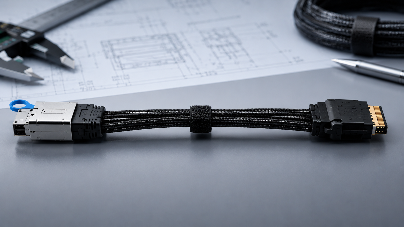
Tell us what the SFF-8654 4i side mates with, what is required at the opposite end, and how the assembly must pass around nearby hardware. A top-view photo, mechanical drawing or existing sample can quickly clarify orientation and clearance.
 Host and target platformBoth endpoint referencesOrientation and clearanceDrawing, photo or sample
We start with the platform, endpoints, quantity and available references.
Clarify direction, lane mapping, plug orientation, length and chassis clearance.
We take the clarified configuration to a suitable manufacturing partner.
We then recommend a quote or sample step that fits the project stage.
If the project needs an 8i path, U.2 endpoints or four SATA devices, choose the corresponding configuration instead of forcing a generic 4i match.
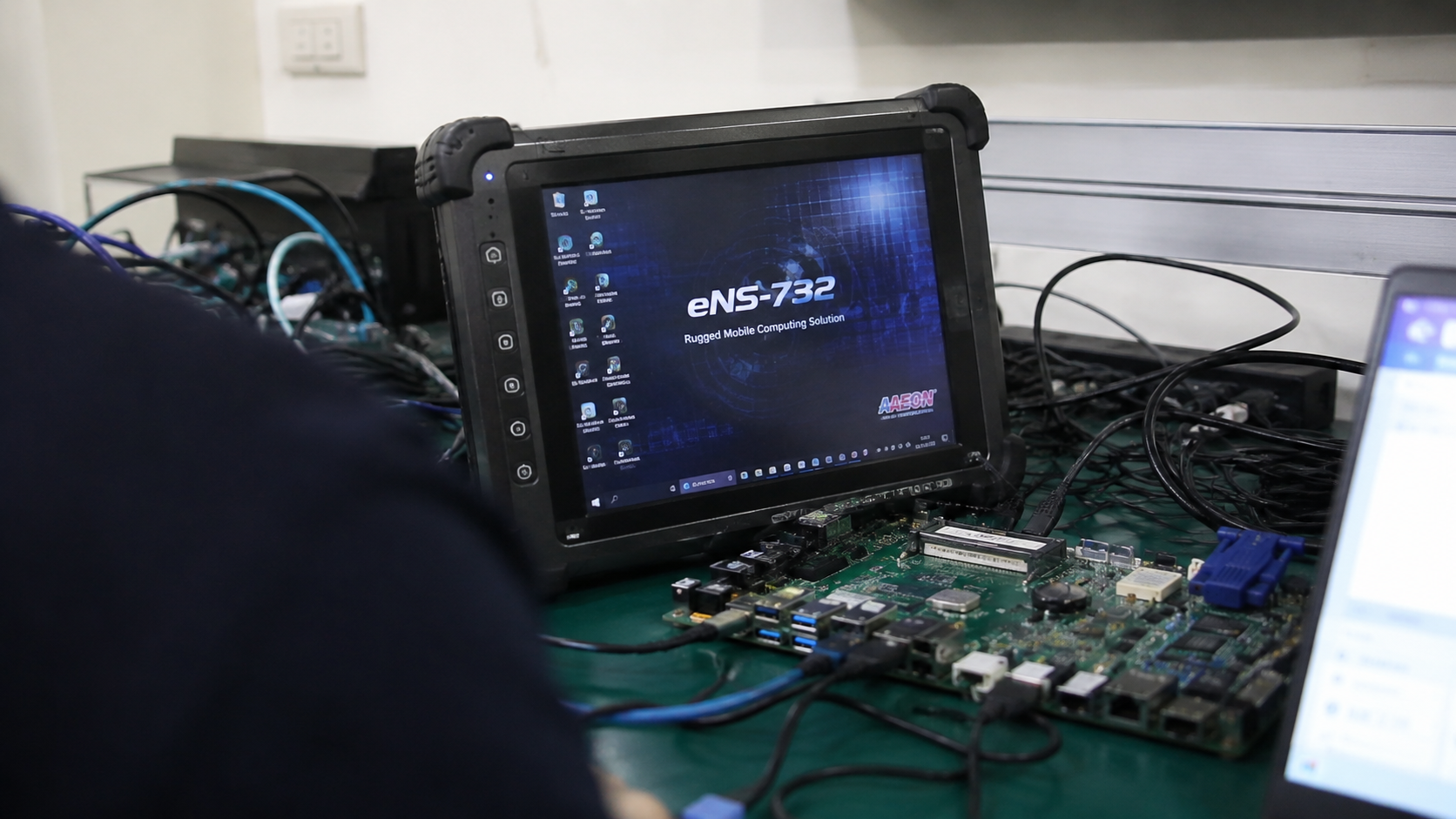
Drive count, power and topology need confirmation.
Review configuration →
Breakout direction, exit and SATA orientation can mismatch.
Review configuration →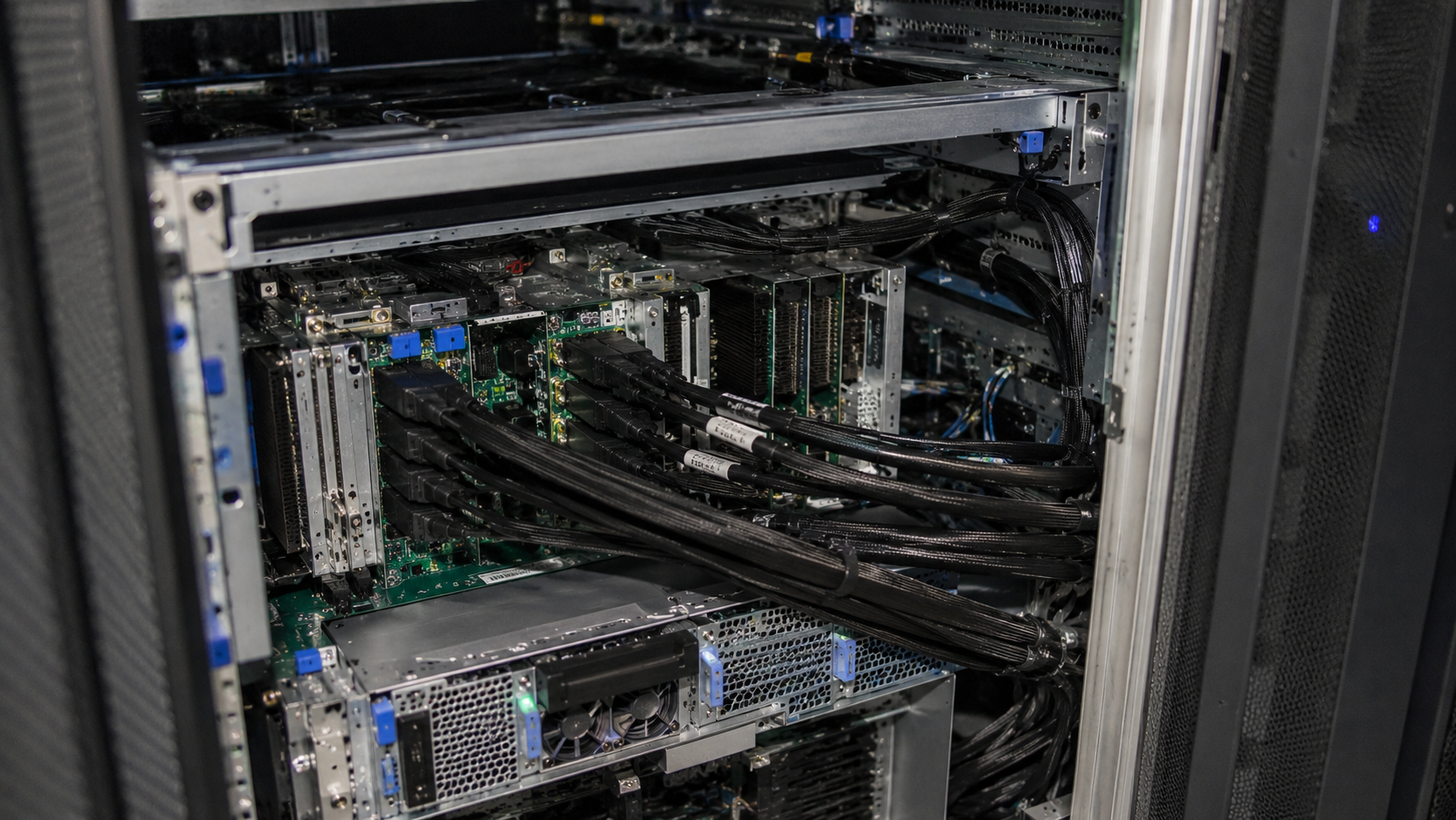
Endpoint, orientation and breakout configuration vary.
Review configuration →01Endpoints02Review 03Partner
 04Quote