 01
01Host, backplane and drive context
Identify the controller or motherboard on the MCIO side and the U.2 device, backplane or drive arrangement on the target side.
An RFQ page built around your requirement for MCIO-to-U.2 storage interconnect projects where drive count, power path, topology, orientation and platform compatibility must be reviewed before quotation.
 EndpointsApplication
 Drawing / sample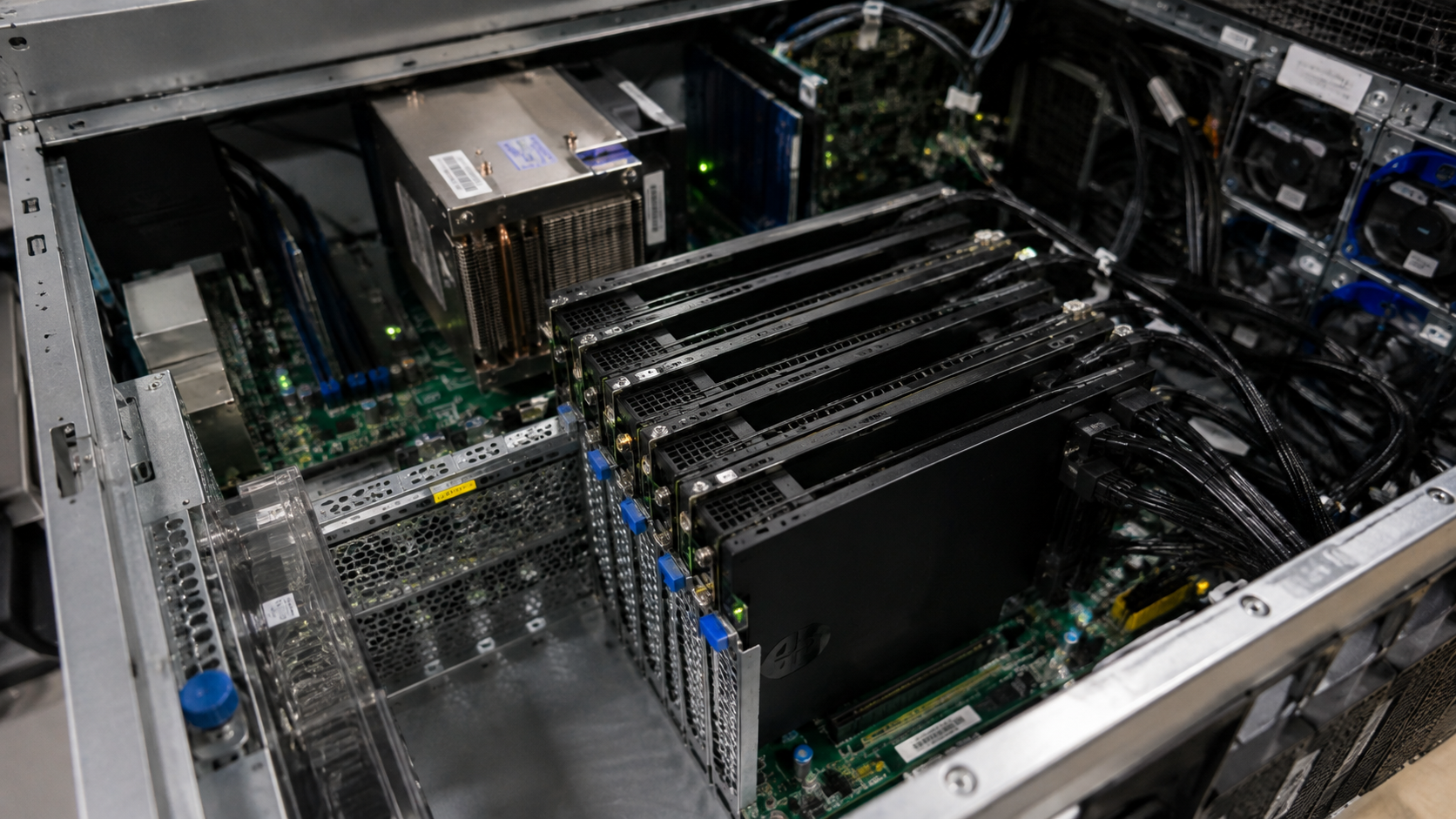
Catalog references support MCIO to U.2 as an RFQ configuration family. They do not establish a universal drive count, power wiring, lane mapping, performance level or system compatibility.
You can start with partial information. Unknown power, topology or endpoint details become explicit questions before quotation.
01Identify the controller or motherboard on the MCIO side and the U.2 device, backplane or drive arrangement on the target side.
02Provide the MCIO connector reference and the required U.2 endpoint count. Photos or drawings help distinguish the intended configuration.
 03
03Explain the intended connection path and drive topology. Lane distribution and mapping are reviewed from project evidence.
 04
04State whether power is part of the requested assembly and provide the applicable platform or wiring evidence. Power is never inferred from the name alone.
 05
05Share connector orientation, cable exit, chassis clearance, routing space and target length where known.
 06
06Provide initial quantity, forecast and whether the project is at concept, prototype, pilot or volume stage.
MCIO-to-U.2 should be selected from the complete storage architecture—not only by matching two connector names.
The assembly supports a different number or arrangement of target endpoints than the project requires.
Power is expected from the cable even though the exact configuration or platform uses another arrangement.
The host, backplane and drive relationship does not match the intended lane distribution.
Cable exit, connector orientation or bend path conflicts with the chassis or drive bay.
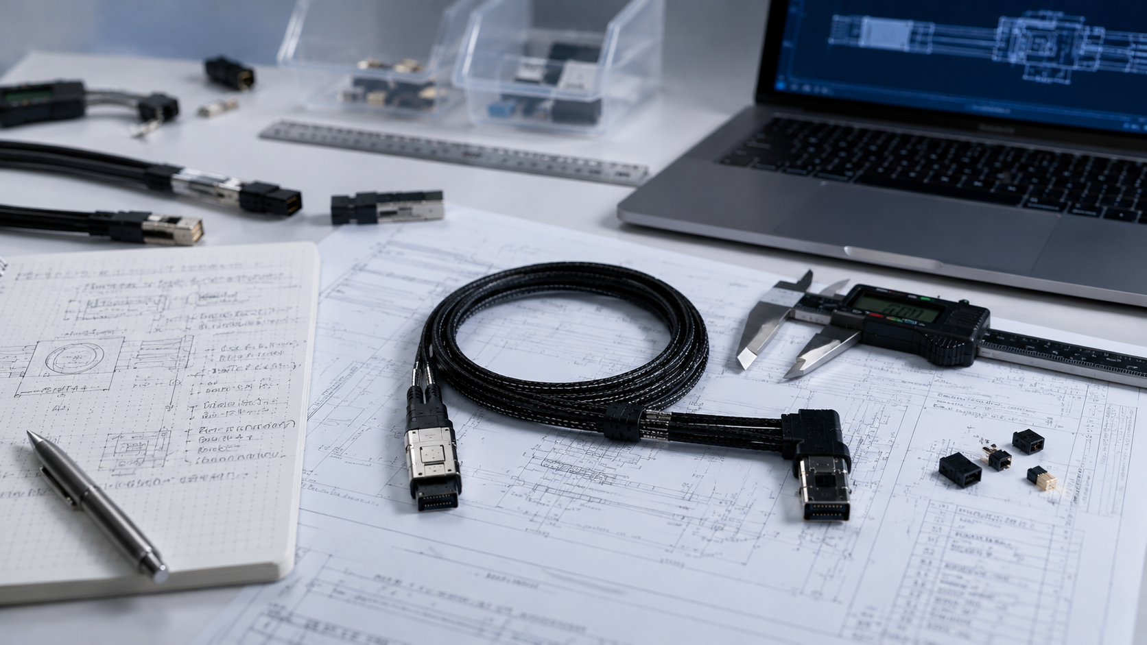
Tell us whether the U.2 side connects directly to a device, through a backplane, or through another system component. Add any power, routing and serviceability constraints that affect the cable assembly.
 Controller and backplaneU.2 drive count and topologyPower evidence or requirementDrawing, photo or sample
We start with the host, U.2 endpoints, quantity and available references.
Clarify drive count, mapping, power arrangement and mechanical constraints.
We take the clarified configuration to a suitable manufacturing partner.
We then recommend a quote or sample step that fits the project stage.
If U.2 is not the actual device-side requirement, select the correct endpoint family or use Custom Cable review.
MCIO size, SlimSAS endpoint and orientation must match.
Review configuration →
Host/target direction and lane mapping can make the wrong cable unusable.
Review configuration →
Endpoint, orientation and length vary by platform.
Review configuration →01Endpoints02Review 03Partner
 04Quote